What this chapter covers
Tool Management connects two kinds of data: information about registered physical tool instances and information that a machine reports about its current tool, magazine and cutting edges. This chapter covers tool types and instances, identifiers, locations and movements, links to machine data, cutting edges, measurements and tool life.
It is assumed that the Tool Management microservice is already installed, connected to DPA Host and synchronised. Installation, database connection and operational verification are covered in the DPA Installation and Operations Guide.
1. Tool objects and data
In Tool Management, the word “tool” is used in several related but distinct senses. This distinction matters from the outset: otherwise a machine-journal record can easily be mistaken for the card of a particular physical tool, or a magazine position for its identifier.
A physical tool instance is an object registered in Tool Management that represents a particular cutter, drill, milling tool or other piece of tooling. An instance has a tool type, generated identifiers, a current location, a movement history and, when measurements have been made, a measurement history. Several physical instances can share the same tool type: the type describes common properties and composition, while the instance represents the particular tracked item.
The current location of such an instance is maintained by Tool Management itself. It can be a storage location or a magazine position of a Work center; moving the instance through its card closes the previous location and starts a new history record. This placement describes the tracked path of the physical instance and does not by itself create a machine record from the controller.
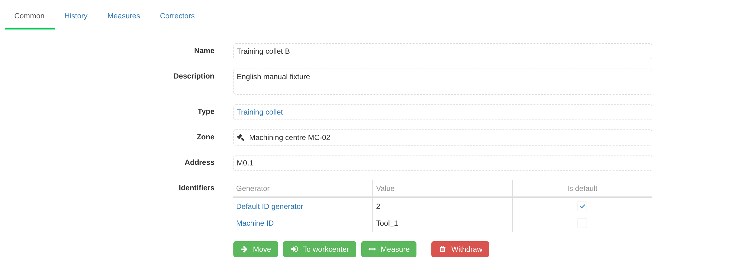
A registered physical tool instance card. The instance has its own tool type, current location and generated identifier, with separate History, Measures and Correctors tabs.
Separately, the machine reports machine tool data. It can contain the Tool ID and tool number, the active-tool channel, magazine and position, cutting-edge numbers and types, their parameters, states and life-monitoring values. Tool Management builds machine history from these events, for example the active-tool history and magazine contents. Such a record exists even when no particular physical instance has yet been matched to it.
Therefore, matching magazine coordinates do not by themselves mean that two records refer to the same physical instance. Manually moving a registered tool into a magazine position and a controller message saying that a tool with a particular Tool ID is in that position are two different data flows. DPA uses a separate identifier-matching strategy to connect them; it is described in Section 5, “Linking an instance to machine data”. When the match succeeds, machine journals and analytics can show the particular instance and its type alongside controller data. When there is no match, the machine data is not lost: it remains linked to the identifiers received from the machine.
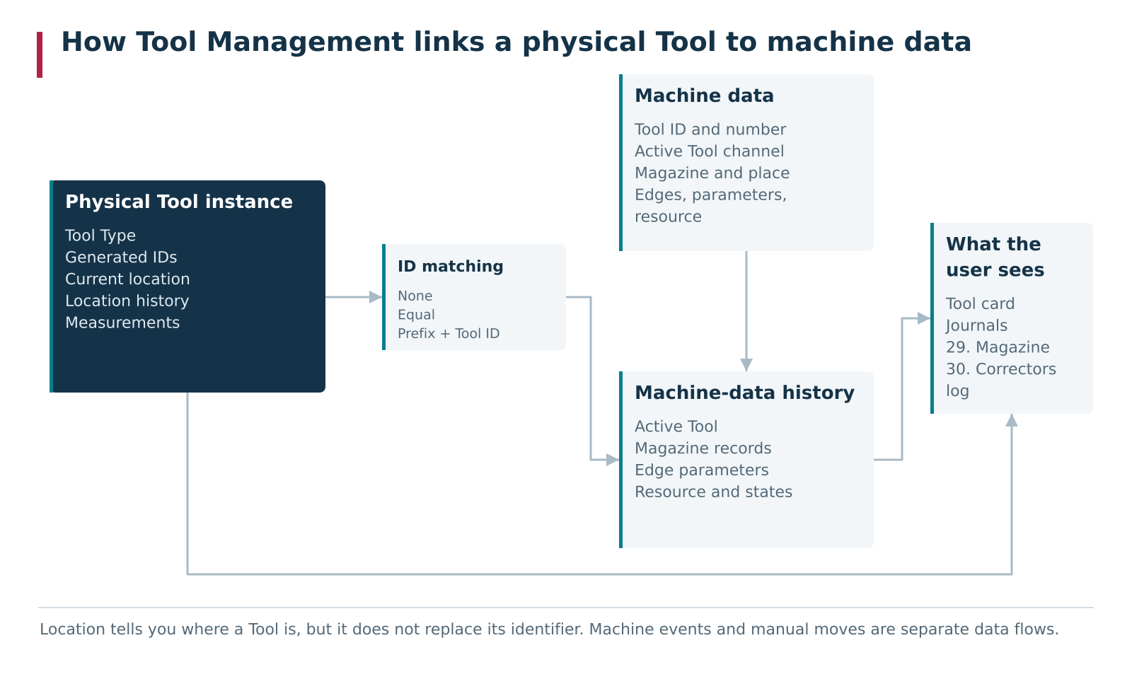
Three layers that must not be treated as one object. A physical instance lives in the Tool Management catalogue, the machine reports its own Tool ID and Tool number, and the service stores separate machine history. A link to the physical instance appears only after identifiers are matched successfully; an identical magazine position does not create that link.
Users work with this model in several parts of the interface:
- the Tool application contains the list of physical instances and Tool types; an instance card combines the Common, History, Measures and Correctors tabs;
- Tool settings contains ID generators, catalogues and presets that define how types, edges, parameters and measurements are described and displayed;
- on a Work center’s settings, the Tool group defines how machine identifiers are matched to registered instances;
Journals → Toolcontains the Active Tool and Magazine journals built from equipment messages;- 29. Magazine analytics shows the state of tools and cutting edges in a magazine, while 30. Correctors log shows the history of changes to cutting-edge parameters.
A practical rule for reading these screens is simple: first determine whether you are looking at a registered physical instance or a record received from the machine. Then check whether the two have been matched. The following sections build this model step by step, from tool types and instance registration to machine data, edges, measurements and tool life.
2. Reference data, tool types and presets
A tool type describes the common construction and properties shared by several physical instances. For example, ten identical end mills can have one tool type, while every physical instance is registered separately and receives its own identifiers and history. It therefore makes sense to configure the type first and register particular tools afterwards.
Open the Tool application and go to the Tool types tab. The list shows Name, Description and Type. You can create a new type manually; importing a GTC package is available separately. Import is covered in Section 9, “GTC import and the connected lifecycle”.
Tool type components
A type does not have to be one indivisible part. Its card can contain several components, for example a holder, milling-cutter body and cutting part. Each component has its own Name, Class, Description, images and set of properties. Component order is retained in the type composition.
A type can use ISO or GTC classification. A component class is selected from the tree of the corresponding catalogue. After a class is selected, the editor provides the property set defined for that class: parameter symbols, names, units and, where the standard defines them, permitted coded values. For example, the ISO class for an end mill provides lengths, diameters, angles, number of cutting edges and other standard parameters.
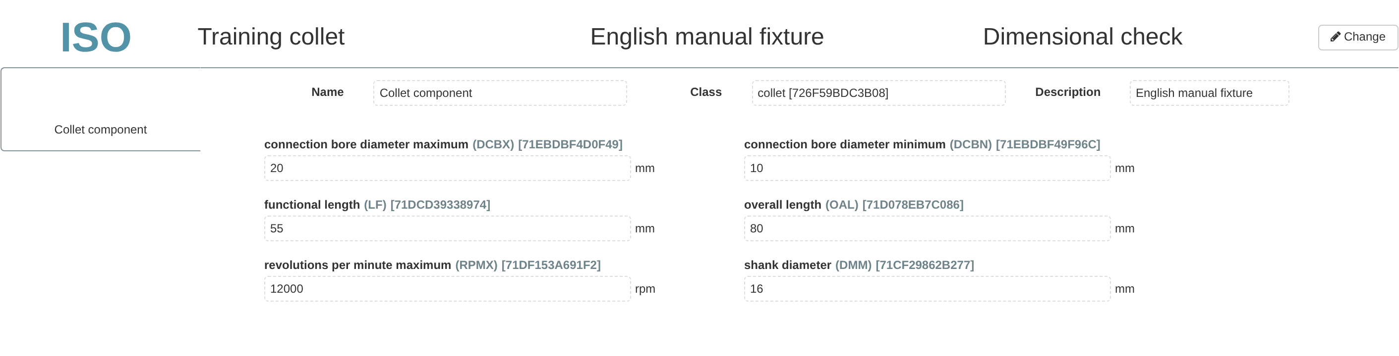
After an ISO component class is selected, the editor exposes the standard properties of that class with symbols and units. The end-mill example shows lengths, diameters, angles and other parameters; fill in only the characteristics relevant to the particular type.
The appearance of these fields does not mean that every one of them must be filled in. The type stores only the values that the user actually specifies. The class therefore defines the dictionary of available characteristics, while the particular tool-type card stores only the subset needed for that type.
At the top of the tool type card you can also select a Measure preset. It does not define the type’s geometry: it is a separate field scheme offered by the Measure command for physical instances of this type. Creating and using measurements is covered in detail in Section 7, “Tool measurements”.
ISO and GTC catalogues
ISO catalog and GTC catalog are available under Tool settings. They are reference books of classes and properties, not lists of registered tools. The tool type editor uses them to classify its components.
The ISO catalog contains the ISO 13399 class tree. Its top level is divided into Assembly Items, Adaptive Items, Tool Items and Cutting Items. Under them are classes for particular components, such as drills, milling cutters, cutting inserts and assembly items.
The GTC catalog provides a similar tree for GTC classification. Selecting a GTC class manually and importing a prepared GTC package are different operations: the catalogue supplies component classification, while package import creates a tool type from the data, images and properties contained in the package.
Symbol presets and edge-type presets
Machine cutting-edge data does not arrive in the terms used by a tool type card. Instead, it arrives as edge-type codes and sets of controller parameters. Tool Management uses two related reference books to interpret and display this data consistently.
A Symbol preset defines known controller parameter symbols and their system meaning. Edge type
presets is the name of the second screen in the interface. Each such preset associates a numeric
cutting-edge type code with a name, icon and a set of parameters from the selected Symbol preset.
For example, the standard SINUMERIK preset contains separate codes for milling tools, drills and other
tool types and specifies which L1, L2, R1, WL1 and other parameters belong to each type.
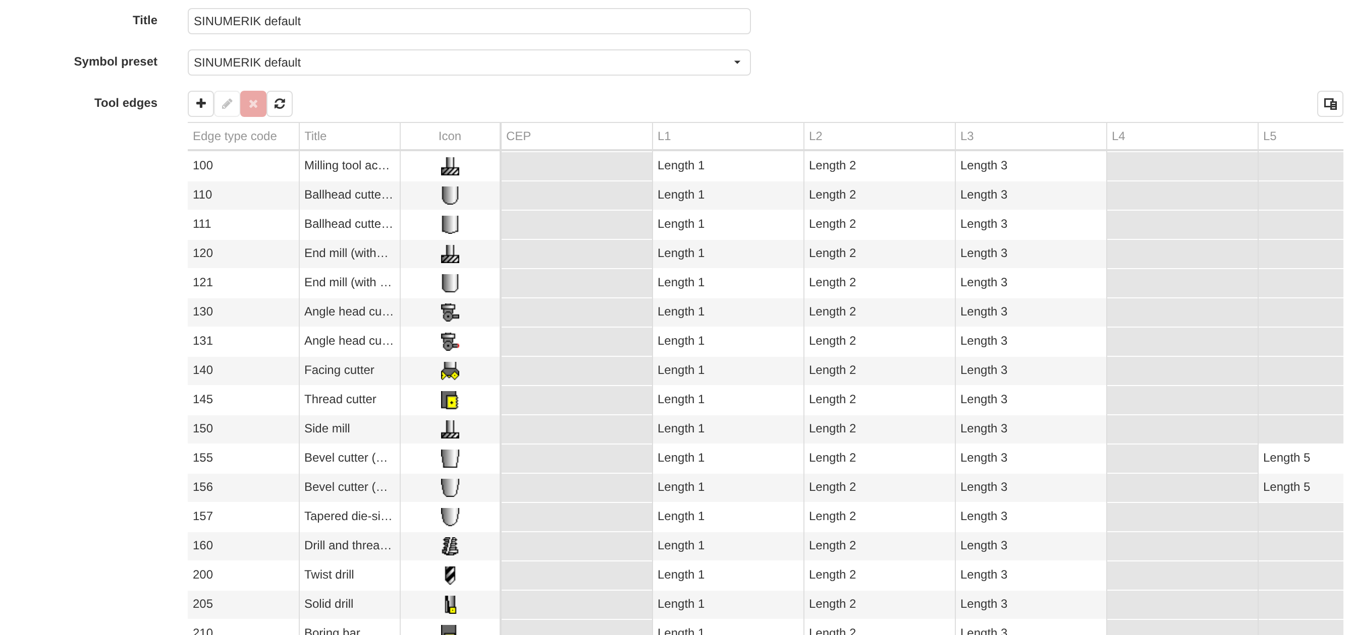
An Edge type preset links controller cutting-edge codes to names, icons and parameters from the selected Symbol preset. In the standard SINUMERIK default, different codes enable their own sets of L1, L2, R1, WL1 and other parameters.
A new Tool Management database contains standard presets for SINUMERIK and HEIDENHAIN. You can use them as ready-made mappings for a supported controller or create your own presets for another set of codes and parameters. A particular Edge type preset is then selected for a Work center; this relationship is covered in Section 5. It affects how machine edge data is displayed in the journal and analytics, but it does not change the construction of the registered physical instance.
Tool Management therefore has two different layers of reference data. The tool type and its components describe what the physical tool is, while symbol and edge-type presets explain how to read cutting-edge data received from equipment. These layers should not be conflated: they meet only when a registered instance is matched to machine history.
3. Registering an instance and generating identifiers
After a tool type has been created, you can register a particular physical instance. From this point Tool Management begins to track it as an independent object: the instance receives its own name, one or more generated identifiers and an initial location. Movements and measurements are later added to the same object and, when matching to machine data succeeds, machine history can be associated with it as well.
Registering a physical instance does not mean that the controller has already detected that tool. It
creates a Tool Management object and places it at the specified storage location. Association with a
machine Tool ID is configured separately and is described in
Section 5.
What must be prepared
Before registration, the following must exist:
- an appropriate tool type;
- a storage location in the DPA structure;
- at least one working ID generator.
A clean Tool Management database already contains the system Standard ID generator with the
{ident} format. No separate generator configuration is therefore required for ordinary sequential
numbering.
The storage location is not an arbitrary string. Tool Management uses an existing DPA address:
Storage zone → Storage unit → Storage location. This chain is required from the first registration,
because a registered physical instance always begins its lifecycle at a particular location.
Registering a physical instance
Open the Tool application, select the Tool tab and click Add. Specify:
- Name — a convenient name for this particular physical instance;
- Description — an optional additional explanation;
- Type — the previously created tool type;
- Address — the storage zone, storage unit and storage location selected in sequence.
After the complete address has been selected, the form shows its combined path.
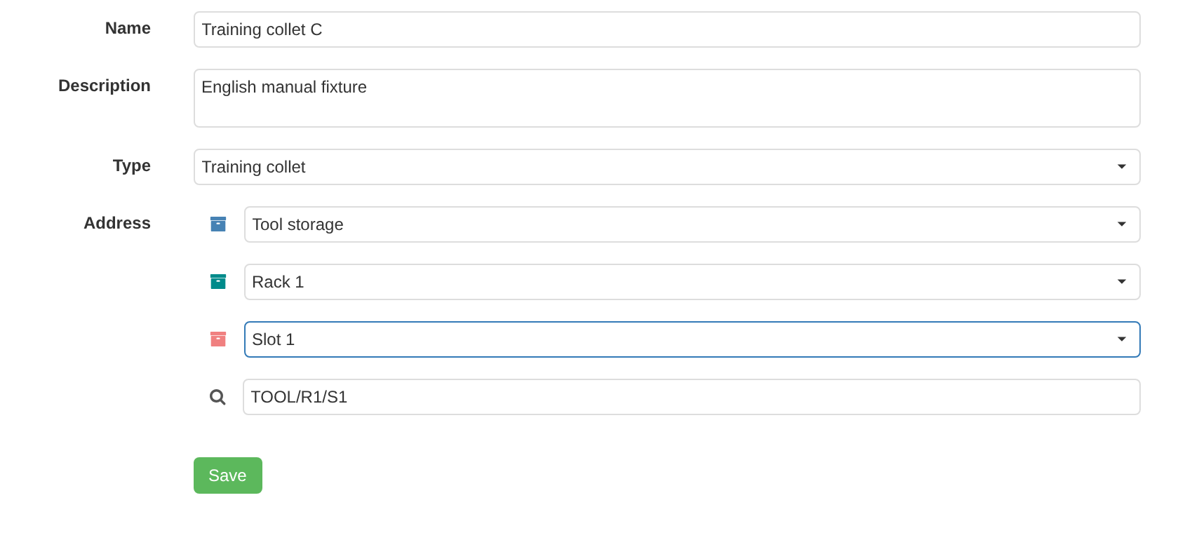
Registration of a physical instance starts by selecting the tool type and a particular storage location. The address is selected as Storage zone → Storage unit → Storage location; DPA then shows the resulting combined path.
Click Save. Tool Management creates a new physical instance, generates its identifiers and records its initial location. In the Tool list, the primary identifier appears alongside the name, type, zone and address. The initial location record becomes the first entry in the instance history; subsequent movements are covered in Section 4.
Registration does not bind the physical object to a machine-magazine coordinate and does not create machine journals. This remains true even if the tool is later placed manually in the same magazine and position reported by the controller: location and machine identity remain separate data layers.
Where the identifier comes from
Open Tool settings → ID generators. For each generator the list shows its Name, Description,
Format, Is default and System flags, and the counter’s Current value.
The standard generator uses the {ident} format. On the first successful registration an instance
receives the value 1, then the counter advances to 2, and so on.
During registration Tool Management runs all configured ID generators. A single physical instance can therefore receive several generated identifiers. The generator marked Is default determines the primary identifier shown in the general list. The other values remain attached to the same instance and can be used later when matching a machine identifier.
A custom ID format
If a simple sequence is not sufficient, create a new generator under Tool settings. Its main field
is Format. The {ident} marker denotes a sequential numeric counter. A new generator offers the
format ID-{ident} and can therefore produce ID-1, ID-2, and so on during registration.
The format can also include {0}, {1} and subsequent parameters. Their values are supplied by the
generator rules. The rule editor is divided into four tabs:
- Default parameters — a fallback independent of tool class;
- Root nodes parametes — rules for broad groups in the ISO classification;
- Class nodes parameters — rules for a particular class, including values taken from properties of a tool type component;
- Assembly parameters — compound rules that can obtain values from several components.
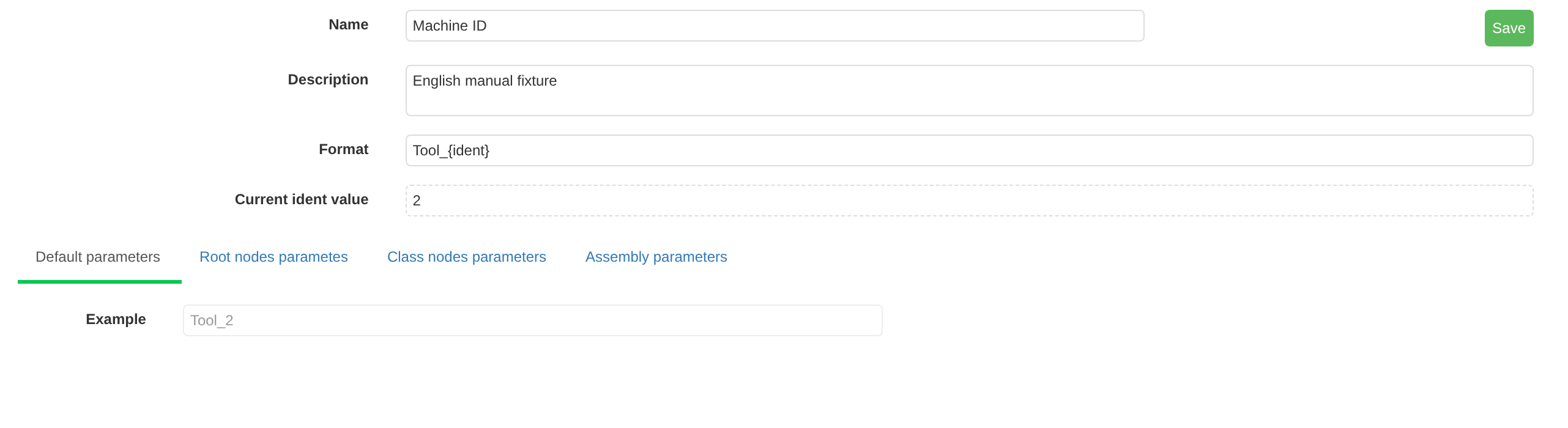
A new ID generator defines an identifier format and rules for filling its parameters. {ident} is a sequential counter; additional parameters can come from default, root-node, class-node or assembly rules.
When generating an ID, Tool Management first tries an assembly rule, then the rule for the particular class, then the root-node rule, and finally the default rule. The first fully applicable rule supplies the parameters for the current tool type. If no rule can provide all parameters required by the format, no identifier is generated and registration ends with an error.
For most installations, the standard {ident} or a simple custom prefix such as F-{ident} is
sufficient. Rules based on ISO/GTC properties are useful only when the identifier structure genuinely
needs to encode the tool type or its properties. An ID is primarily a stable identifier of a
physical instance; it should not be overloaded with information already stored in the tool type
card.
4. Location, movement and history
After registration, a physical instance always has a current location. While a tool is in storage, Tool Management shows its Storage zone and combined Address. When the instance is installed in a machine magazine, the storage address is replaced by the Work center and magazine position. A user can therefore open the Tool list or instance card and see where the item is currently recorded.
Location belongs specifically to the registered physical instance. It is changed manually by Tool Management actions and retained in the instance’s own history. Controller records about the magazine and active tool form a different data flow; their relationship to the physical instance is covered in Section 5.
Moving between storage locations
To move a tool from one storage location to another, select the instance in the Tool list and
click Move. In the Tool move window select the new location using the same hierarchy as during
registration: Storage zone → Storage unit → Storage location. DPA shows the resulting combined
address. If necessary, fill in Reason and click Move.
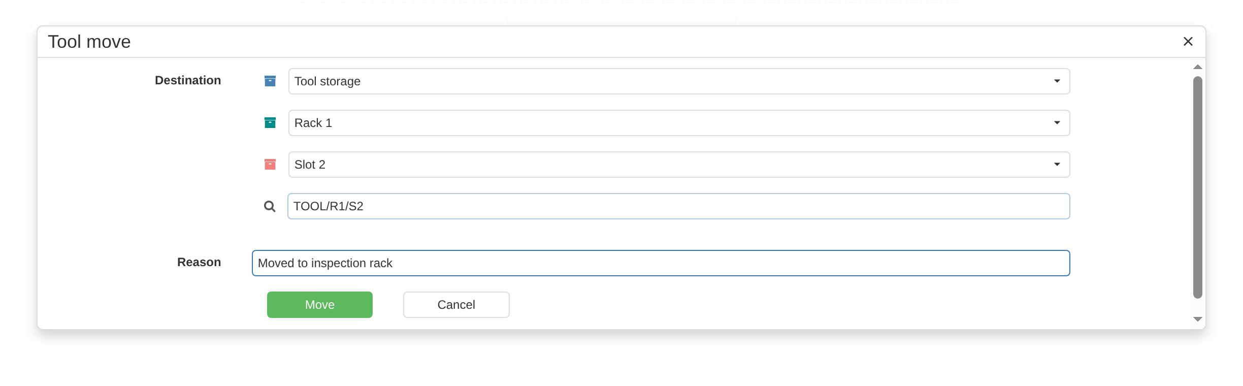
Move selects a new storage location using the same hierarchy as registration. DPA shows the combined destination address; a reason can be added when required.
After saving, the new address becomes current. The previous location does not disappear: its interval is closed at the movement time and remains in the instance history. The sequence of movements can therefore be reconstructed later rather than only the latest address being visible.
Installing a tool in a machine magazine
For a physical instance being transferred to a machine, use To workcenter. The Install into
magazine window lets you select a Work center, magazine and particular position. After
confirmation, the storage location is closed and the selected magazine position becomes current. The
magazine position is shown in the instance card as a combined address such as M0.1.
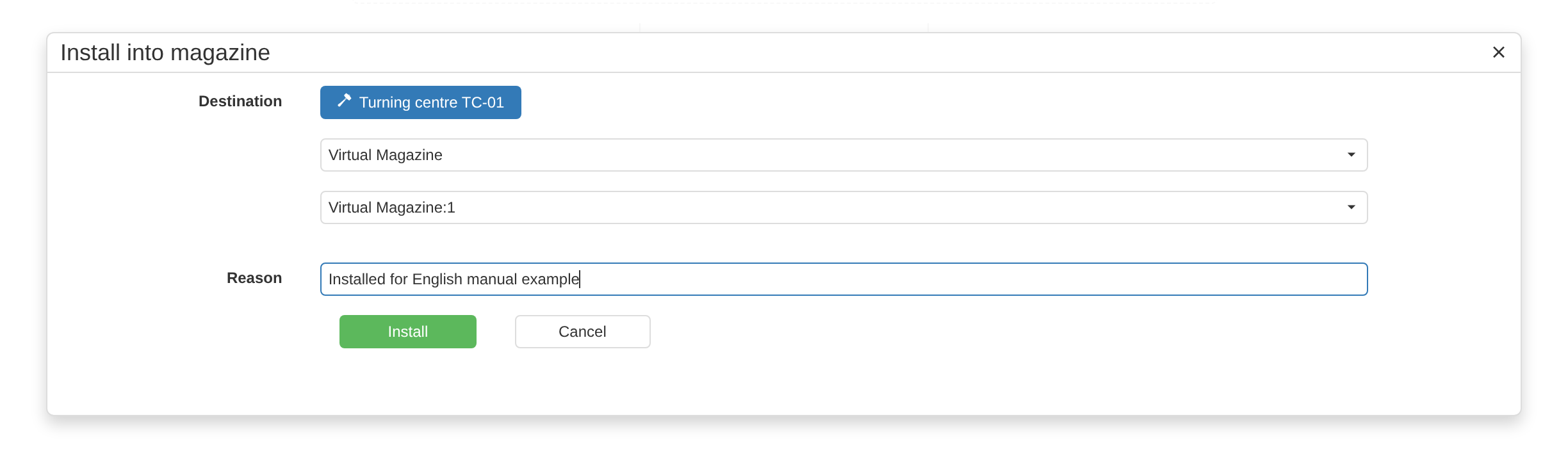
To workcenter selects a Work center, magazine and a particular position. After confirmation, this position becomes the physical instance’s current location in Tool Management.
To workcenter changes only the physical instance’s location in Tool Management. It does not by itself create a machine-journal record and does not prove that the controller reported the same tool. Even if the selected position matches a magazine coordinate in machine data, identity matching is performed separately.
Reading location history
Open the instance card and go to the History tab. For each period it shows:
- From — when the tool entered this location;
- Until — when it left; the field remains empty for the current location;
- Address — the storage location or machine-magazine position.
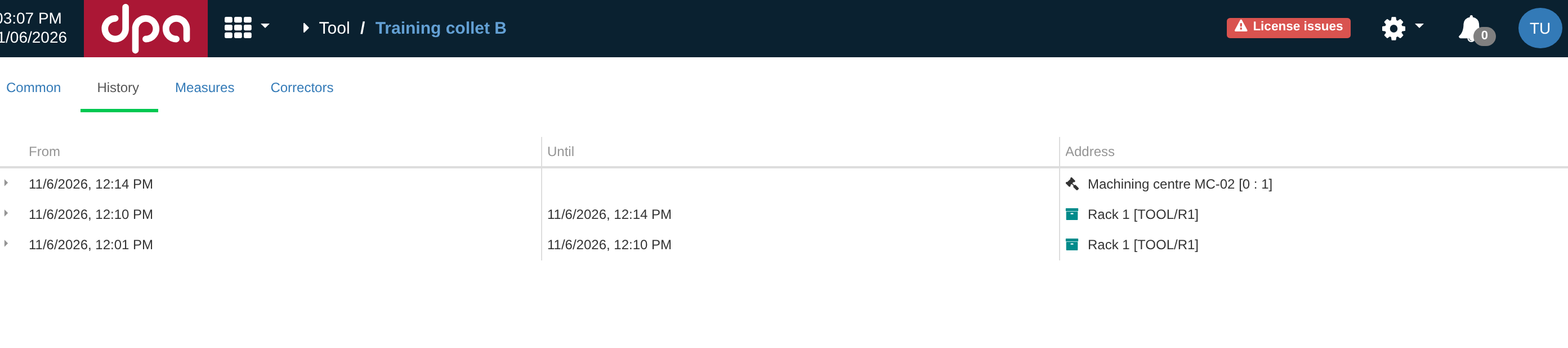
The History tab stores a separate period for every location of the physical instance. Completed periods have both From and Until values, while the current row remains open; this example shows two completed storage periods followed by the current M0.1 machine-magazine location.
Each row represents a separate location period. After a sequence such as P1 → P2 → M0.1, the first
two rows have both a start and an end, while the magazine row remains open as the current state.
Expand a row if you need to see which action created it, which user DPA stored for that action and
what Reason was specified for the movement.
The history is useful for more than finding a tool. It reconstructs the path of the physical instance and keeps an actual manual movement distinct from machine events that might have arrived at a different time or not at all.
Withdrawing an instance
When a physical tool should no longer take part in normal circulation, select it and click Withdraw. Specify a Reason if required. Tool Management closes the current location, records the withdrawal action and moves the instance into the withdrawn state.
Such instances are hidden from the normal list by default. Enable Show withdrawed to display them alongside active ones. Previously occupied locations remain in history; withdrawal closes the instance’s current route rather than erasing its earlier movements.
5. Linking an instance to machine data
A machine controller and Tool Management describe a tool from different perspectives. The controller reports a machine Tool ID, tool number, active channel, magazine and position. Tool Management separately stores registered physical instances and their generated identifiers. To show a particular physical instance in machine history, these identities must be matched.
Matching is configured separately for each Work center. Open its card, go to the Settings tab and find the Tool group. It contains Edge type preset, Tool Id strategy and, for the prefix strategy, Prefix. The edge type preset is needed for cutting-edge data and is covered in Section 6.
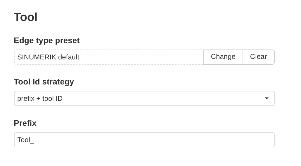
In the Tool group of a Work center’s settings, select how a machine Tool ID is matched to identifiers of registered physical instances. The prefix strategy additionally requires the exact Prefix string.
Matching strategies
Three options are available under Tool Id strategy.
| Option in the interface | How a physical instance is found |
|---|---|
| none | The machine record is stored without searching for a registered instance. |
| tool ID | The machine Tool ID is compared with generated IDs of registered instances. |
| prefix + tool ID | The value of Prefix is prepended to the machine Tool ID, and the resulting string is compared with generated IDs. |
Matching is not limited to the primary ID shown in the general Tool list. If an instance received several identifiers from different ID generators during registration, any of these generated IDs can be used for matching.
For example, suppose a physical instance has identifiers 2 and Tool_1. The results are:
| Work center setting | Tool ID from the machine | String searched by Tool Management | Result |
|---|---|---|---|
| none | 2 | no search | machine record without an instance |
| tool ID | 2 | 2 | physical instance found |
prefix + tool ID, prefix Tool_ | 1 | Tool_1 | the same physical instance found |
The strategy is applied when a new machine record arrives. Changing the setting does not rebind old history retroactively. After changing the strategy, verify the result on a new event from the machine.
What appears in machine journals
Open Journals → Tool. It contains two separate journals:
- Active Tool — active-tool history by Work center channel;
- Magazine — history of magazine-position contents.
Both journals retain machine Tool IDs and numbers regardless of whether a physical instance was found. If matching succeeds, the Tool instance and information about its type are shown alongside the machine data. If no generated ID matches, or none is selected, the machine record remains in the journal but the instance field is empty.
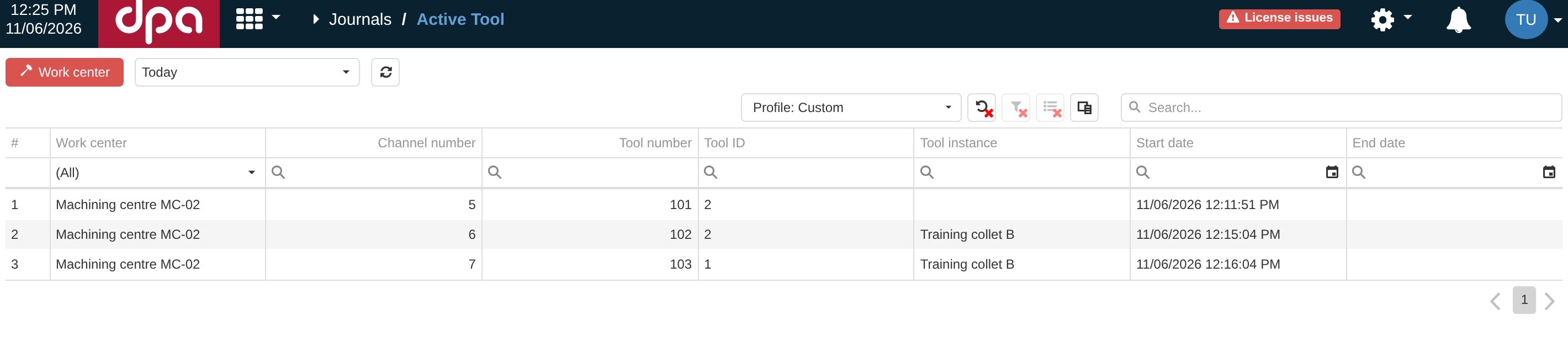
Machine IDs and numbers are always stored in Active Tool. With none, the instance field remains empty; with tool ID and prefix + tool ID, the same machine data can be linked to a registered physical instance.
For example, with the none strategy, machine ID = 2 remains without a physical instance. After
selecting tool ID, a new record with the same ID = 2 can be linked to the instance; with
prefix + tool ID, machine ID = 1 and prefix Tool_ produce the lookup value Tool_1.
Why a magazine position does not identify the instance
Magazine coordinates and the current location of a physical instance do not take part in selecting a match. They answer a different question: where the tool is or is recorded as being. The ID strategy answers which particular physical instance corresponds to the machine record.
Therefore, an identical magazine position does not link the data by itself. Conversely, a matching generated ID can associate a machine record with an instance even when its manual Tool Management location has not yet been brought into line with the actual machine state. Treat such a discrepancy as a sign of inconsistent data and check the instance location separately.
If an instance was not matched
Check the chain from identifiers through to a new machine event:
- Open the physical instance card and verify that its generated IDs include the value the selected strategy should produce.
- In the settings of the required Work center, check Tool Id strategy and, for prefix + tool ID, the exact Prefix value.
- Compare the machine Tool ID in the journal with the expected matching string.
- After changing the setting, wait for or create a new machine event; already stored rows do not test the new strategy.
- Do not use a matching magazine and position as proof of identity: coordinates and IDs solve different problems.
Once a machine record is linked to a physical instance, that relationship becomes especially useful for the history of cutting-edge parameters and correctors. These are covered in Section 6, “Cutting-edge data and the Correctors log”.
6. Cutting-edge data and the Correctors log
A machine record for a magazine position can contain not only a Tool ID and tool number but also information about its cutting edges. For each edge, the controller reports its number, type code and a set of parameters. This data belongs to machine history: it appears from equipment events, not from the tool type card and not from manual measurements of the physical instance.
How Tool Management reads edge parameters
On a Work center, an Edge type preset is selected in the Tool settings group. It associates an edge-type code with a name, icon and a set of symbols from the related Symbol preset. This turns a controller parameter string into labelled interface columns.
For example, in the standard SINUMERIK mapping, edge type code 100 corresponds to a milling tool.
The preset knows parameters such as L1, L2, L3, R1, WL1, WL2, WL3, WR1, BL1, BL2,
BL3 and the other defined symbols. If the machine reports, for example, L1 = 2.5 and R1 = 5, Tool
Management can display them as Length 1 and Radius 1 rather than as unknown technical keys.
Only records whose edge-type code could be associated with a type in the selected preset appear in the Correctors log. If the log is empty, first check the Edge type preset of the required Work center and make sure it contains the code actually reported by the controller.
Tool Management does not create a new parameter record for every identical signal. For one magazine position and edge number, a new record is created when the edge type or the set of its parameters changes. Repeating an unchanged value does not inflate the history with duplicates.
Analytics “30. Correctors log”
Open Analytics → 30. Correctors log, select a Work center and a period. The result is displayed in
an Interactive table, so column filters, sorting, selecting only the needed columns
and saved profiles are especially useful for long histories. The table stores:
- the time of the change;
- the physical Tool instance, when the machine record was matched to one;
- machine Tool ID and Tool number;
- edge number, code and edge-type name;
- zone and address of the magazine position;
- dynamic parameter columns defined by the selected preset.
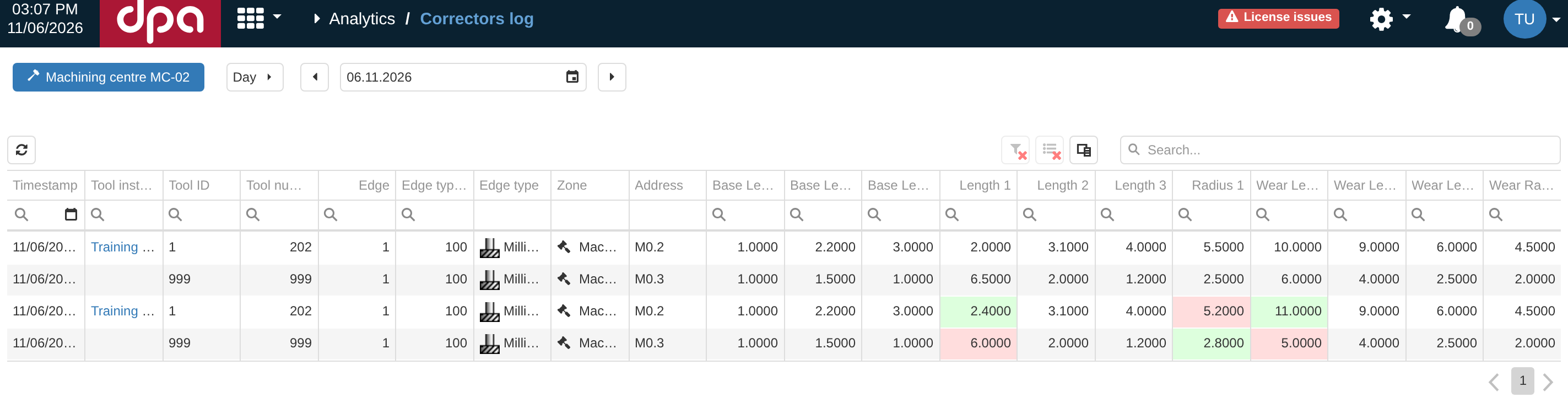
In Correctors log (No. 30), matched rows show the physical instance while unmatched rows are retained under the machine ID. A numeric parameter changed from the preceding record is highlighted: increases in green and decreases in red.
When a machine record is matched to a physical instance, the table shows that instance in the corresponding column. For an unmatched record the column remains empty, but the edge parameters are still stored: the absence of a physical instance does not remove machine history.
When a new record is compared with the previous one, changed numeric parameters are highlighted. An
increase is shown in green and a decrease in red. For example, on the next change Length 1 can fall
from 2.5 to 2.0, Radius 1 can rise from 5.0 to 5.5, and Wear Length 1 can fall from 12 to
10. The highlighting indicates the direction of parameter change, not whether the tool has
changed for better or worse.
How the history of one edge continues
To compare values meaningfully, Tool Management must determine which rows represent the same physical edge over time. The key depends on whether the machine record could be matched to a registered instance:
- if the Tool instance is known, previous parameters are searched by physical instance + edge number;
- if the instance was not found, the fallback key is machine Tool ID + edge number.
For a matched tool, history can therefore follow one physical instance even when other machine attributes change. An unmatched tool has no such stable physical identity, so Tool Management must treat the same machine Tool ID as continuation of the same edge.
This is useful, but its boundary matters. If the controller reuses the same Tool ID for different physical tools, unmatched history can appear as one continuous sequence. If keeping histories of different physical tools separate matters, configure ID matching first as described in Section 5.
Correctors for a particular physical instance
When machine records are matched to a physical tool, the same history can be opened directly from its card on the Correctors tab. The instance context is already fixed there, so a separate Tool instance column is unnecessary: the table shows only changes linked to this particular physical object.
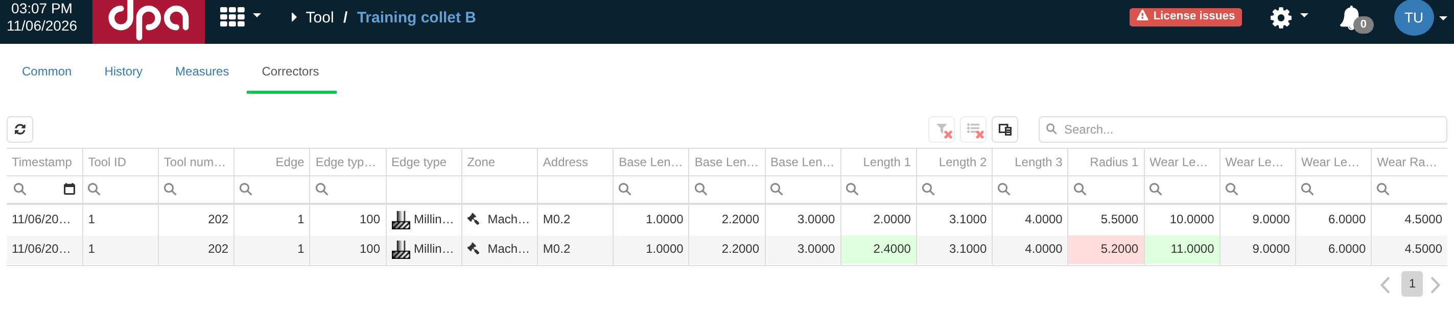
The Correctors tab of a tool card shows only machine changes that were matched to this physical instance. Unmatched rows from the global log do not appear here.
This tab is especially convenient when tracing one milling tool or drill through a sequence of machine events. The global Correctors log, by contrast, is better suited to comparing different tools, Work centers and unmatched machine records over a period.
Correctors and tool life are different data
The name Correctors log does not mean that Tool Management calculates remaining tool life from
this table. It stores snapshots of cutting-edge parameters and their changes. Such parameters can
indeed include fields named, for example, Wear Length 1, but to the service they are still values
reported by the controller as part of the edge parameter set.
Separately, equipment can report life-monitoring values: remaining value, desired value and a pre-warning threshold for operating time, number of workpieces and other monitoring types. This data is stored separately from correctors and is covered in Section 8, “Cutting-edge life and states”.
If the Correctors log does not show an expected change, check in order: whether the correct Work center and period are selected, whether the correct Edge type preset is assigned, whether the preset contains the edge code actually reported by the controller, and whether the parameter set really changed relative to the preceding machine event.
7. Tool measurements
Measures in Tool Management form a separate measurement history for a particular physical instance. They are entered explicitly by a user; they do not come from the machine journal and do not replace cutting-edge parameters, correctors or life-monitoring values. A measurement is useful when, after setup, regrinding, inspection or another operation, you need to record the tool’s actually measured dimensions and later see who registered them and when.
The set of fields for a measurement is defined in advance by a Measure preset. The same preset can be assigned to a tool type, after which the Measure command on physical instances of that type offers the same input form.
Configuring a Measure preset
Open Tool settings → Measure presets and create a new preset. Specify Name, then add the required
fields with Add field. Field names become labels in the measurement dialog and in saved history.
For example, for a simple milling-tool check you can create Diameter and Length fields.
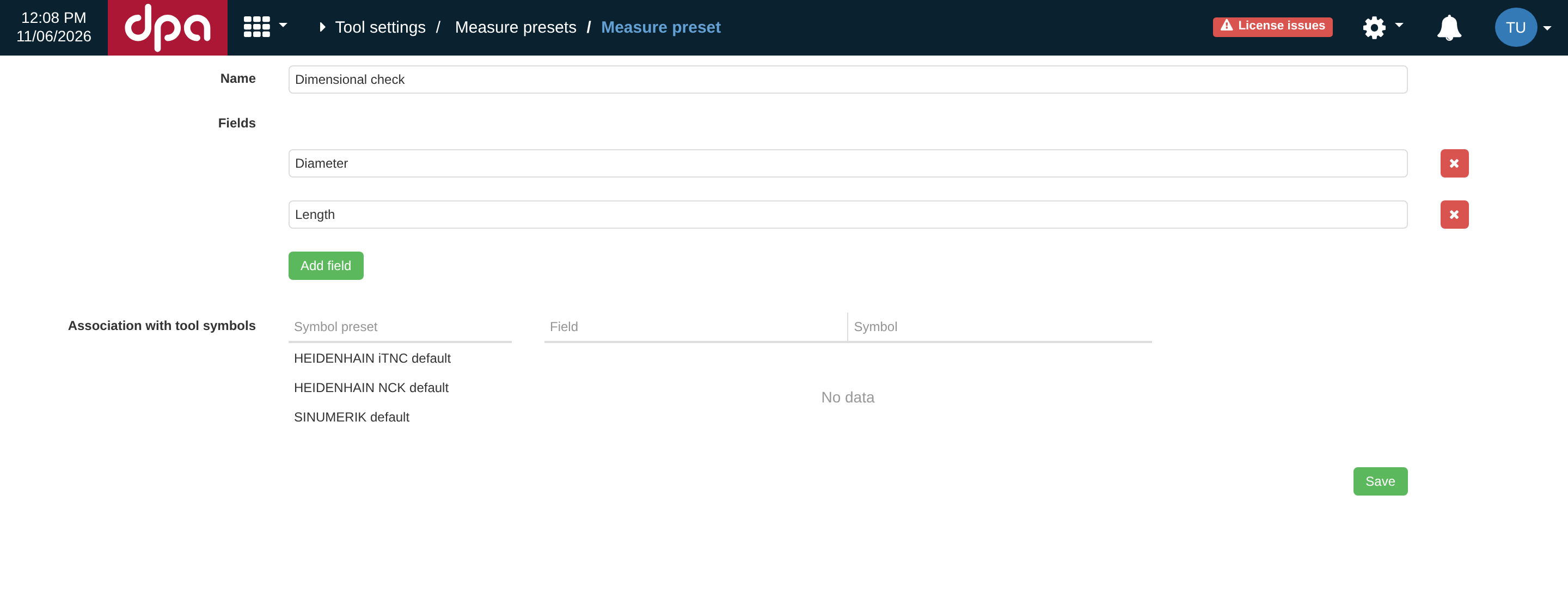
A Measure preset defines the fields shown to the user by Measure. The fields work on their own; when needed, they can also be associated with symbols from the selected Symbol preset.
At the bottom of the editor is Association with tool symbols. Here a measurement field can be linked to a symbol from one of the Symbol presets. This association is optional for ordinary manual input: a preset with named fields also works without it. Use the association when your process needs the measurement field to be explicitly linked to the adopted tool-symbol system.
Save the preset, then open the required tool type and select it in Measure preset. The preset is assigned to the type, not to an individual physical instance, so the same field set can be used for all registered tools of that type.
If a tool type has no preset assigned, Measure does not show the ordinary field form. The interface reports that the tool type has no measurement preset and offers to go to its configuration.
Recording a measurement
Open the physical instance card and click Measure. The dialog contains the fields from the current Measure preset of its tool type. Enter the actually measured numeric values and click Save.
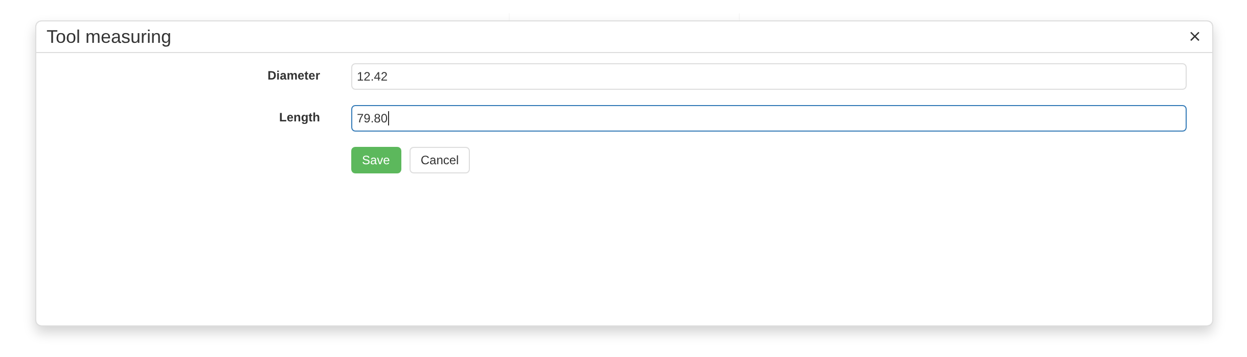
Measure opens the fields of the Measure preset assigned to the tool type. Saving creates a new measurement record specifically for the current physical instance.
When saved, Tool Management creates a new record specifically for the selected physical instance. It stores the time, user, preset used and the values of its fields. The measurement itself does not change the tool type, current location, association with a machine Tool ID, correctors or cutting-edge life.
A later measurement does not overwrite the previous one. For example, you can first save
Diameter = 12.5 and Length = 80, and later 12.42 and 79.8. Both results remain as separate
history records.
Instance measurement history
Open the Measures tab of the tool card. For each record the table shows Measure date, Preset and User. Expand a row to see all saved measurement field values.
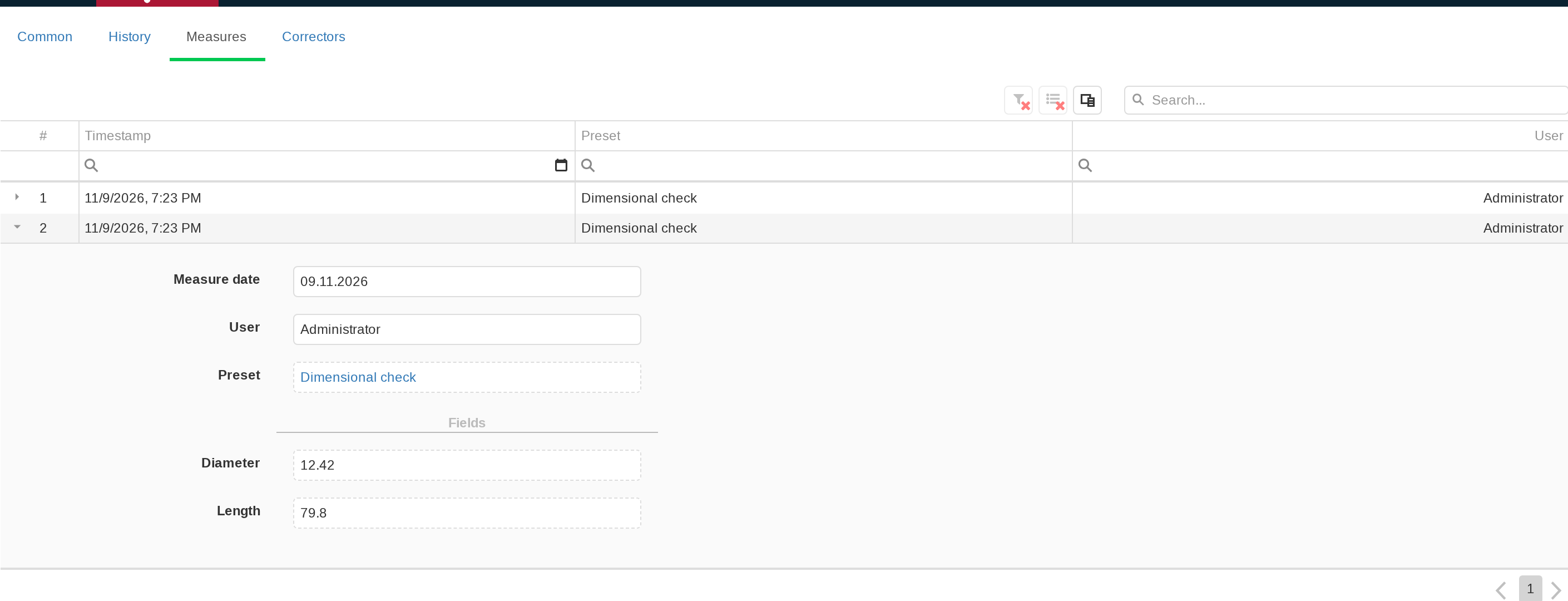
The Measures tab accumulates separate records. An expanded row shows the user, preset used and saved field values, while previous measurements remain in history.
The history belongs to a particular physical instance: two milling tools of the same tool type have different sets of Measures records even when both use the same preset. The table does not offer editing or deletion of an already saved measurement; when a new actual state must be recorded, perform another measurement and create a new history row.
A practical way to read this mechanism is:
- a Measure preset defines which values must be entered;
- a tool type defines which preset is used;
- Measure stores one actual result for a particular instance;
- the Measures tab retains the sequence of those results over time.
Do not confuse this history with the Correctors log from Section 6. Correctors arise from machine cutting-edge events, while measurements are created by an explicit user action for a physical instance. Remaining-life values for edges are another separate flow and are covered in Section 8.
8. Cutting-edge life and states
Parameters in the Correctors log show how cutting-edge values changed, but they are not by themselves a calculation of remaining tool life. Separately, the controller can report life-monitoring values and current tool states for each edge. Tool Management stores this machine data and displays it in Magazine analytics.
Life-monitoring values reported by equipment
Several monitoring types can arrive simultaneously for the same edge number. Tool Management supports four meaningful types:
| Monitoring type in the interface | What it represents |
|---|---|
| Tool life | a separate tool-life monitoring channel; the scale and units are defined by the machine-data source |
| Number of workpieces | remaining life expressed as a number of workpieces |
| Edge wear limit | separate monitoring of the cutting-edge wear limit |
| Total length wear limit | separate monitoring of the total wear limit by length |
Tool Management does not define the units for these values itself: they depend on how the controller or driver supplies the corresponding measure. Three numbers are reported for each monitoring type:
- Remaining — the current remaining value;
- Desired — the target value used to build the scale;
- PreWarning — the pre-warning boundary.
These values come from the equipment. Tool Management does not calculate Remaining from corrector
history, physical-instance measurements or time spent in the magazine. If the controller does not
report edge monitoring, the service has no basis from which to reconstruct it.
Analytics “29. Magazine”
Open Analytics → 29. Magazine and select one or more Work centers. The screen uses the magazine
configuration defined in the enterprise structure and shows the latest known machine state of their
positions. It is a current view of the magazine, not a journal for a selected period.
For an occupied position, the machine Tool ID is displayed and, when matching succeeds, the physical Tool instance and its tool type are shown as well. Cutting edges, their parameters, life-monitoring values and tool states appear below. Matching from Section 5 therefore enriches the view with a link to the physical object, while the life data itself remains machine data.

Magazine (No. 29) combines the current machine state of a position: the matched physical instance, tool states, an edge and its parameters, plus separate life-monitoring bars. The black marker shows Remaining; the coloured-zone boundary is set by PreWarning relative to Desired.
Each life-monitoring value is drawn as a separate bar. A black vertical marker shows Remaining
relative to Desired, while PreWarning defines the boundary of the warning zone. When the remaining
value falls below that boundary, the warning portion of the scale is highlighted red. While the value
is above the threshold, the warning portion remains yellow and the working range green. Hover over a
bar to see exact Remaining / Desired values and the warning value corresponding to PreWarning.
For example, with Tool life values Remaining = 20, Desired = 120 and PreWarning = 30, the
current marker is already below the warning boundary. For Number of workpieces, values
640 / 1000 with a threshold of 200 are still above the boundary. Both wear-monitoring types can
likewise be shown simultaneously for the same edge.
The screen shows the latest known value of each monitoring type for the current magazine-position
record. When the controller reports a new combination of Remaining, Desired or PreWarning, Tool
Management stores the change; repeating the same three values does not require a separate new record.
Tool states
To the left of the edge data is a row of icons representing the current tool state. These flags are independent, so several can be active at the same time. A highlighted icon means the corresponding flag is present in the latest machine state; inactive flags are grey. The interface provides these states:
- Active tool;
- Enabled;
- Disabled;
- Measured;
- Pre warning limit reached;
- Tool being changed;
- Fixed location coded;
- Tool was in use.
Several states can be active simultaneously. For example, a controller can mark a tool as Enabled, Measured, Pre warning limit reached and Tool was in use; the remaining icons then stay grey.
The numeric PreWarning value on a life bar and the Pre warning limit reached state are two
different machine-data fields. The bar is built from the values of a particular monitoring type,
while the icon reflects a state flag reported by the controller. Tool Management shows both side by
side, but it does not reconstruct the state flag from corrector history or other physical-instance
data.
Reading tool life and corrector history together
When analysing the state of an edge, it is useful to separate the questions:
- What does the controller currently report about remaining life? — use
Analytics → 29. Magazineand the monitoring bars. - Which geometry and corrector values changed over time? — use the Correctors log from Section 6.
- Which manual inspection measurements were made for the physical instance? — use the Measures tab described in Section 7.
These views can refer to the same physical tool, but they do not replace one another. In particular, Tool Management does not build its own predictive wear model from corrector or measurement history and does not calculate a mandatory replacement time. Replacement decisions must use the rules and values adopted by the enterprise and actually reported by the equipment.
If expected life data is absent from Magazine, check in order: whether the required Work center is selected, whether its magazine is defined in the enterprise structure, whether a current machine record exists for the required position, whether the controller reports cutting-edge data, and whether the event contains the required monitoring types. If the tool and edge parameters are visible but the life bars are not, this normally means that the corresponding monitoring values are absent from machine data, not that the registered physical instance is missing.
9. GTC import and the connected lifecycle
Importing a tool type from a GTC package
When tool data has been prepared in GTC format, a tool type can be created from a ready-made package instead of transferring its components and properties manually. Import creates the tool type itself: physical instances are still registered separately afterwards, receive their own identifiers and start their own location histories.
Open the Tool application, select the Tool types tab and click Import on the list toolbar. In the Import GTC package window select a ZIP file and click Upload.
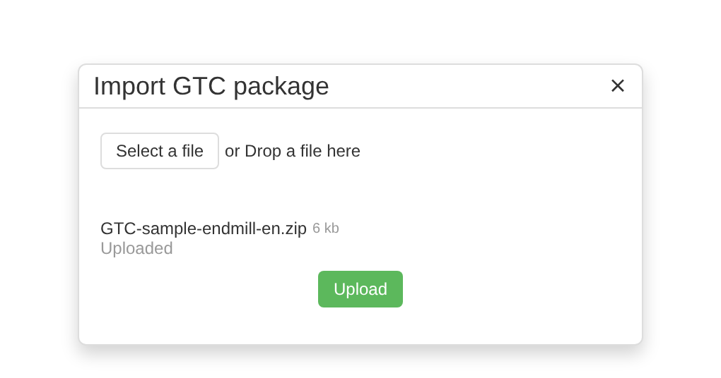
Import is performed in the separate Import GTC package window. After selecting a compatible ZIP, click Upload; the importer rejects an ordinary archive without the GTC structure.
A GTC package has a defined internal structure and contains product descriptions and associated data; an arbitrary ZIP archive is not suitable for import. Use a package supplied by a tool vendor or by another system that produces compatible GTC data.
After successful processing, DPA opens the card of the created tool type. The list identifies its type as Imported from GTC. Tool Management retains the original archive and transfers supported component information from the package: names, classes, properties with their values and units, and related images and drawings. Download GTC package in the card lets you retrieve the saved original ZIP.
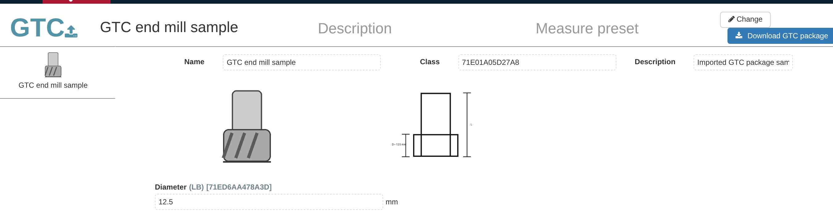
A successful import creates an ordinary tool type card marked as GTC. In this package example, the class, a numeric property with its unit and two related images were imported; the original archive is available through Download GTC package.
Review the imported type before registering physical instances: the composition and completeness of the card depend on the package contents and the supported data types. If a ZIP file is not recognised as a GTC package, the import window reports Import error. Wrong file format. A failed upload does not by itself create a ready tool type.
Import does not configure matching to a controller Tool ID and does not create a Measure preset. If measurements are required for the type, assign a preset separately as described in Section 7.
After opening an imported type with Change and then clicking Save, its association with the original GTC package is removed and Download GTC package is no longer shown. The same happens when a Measure preset is assigned, because this saves the type card. Tool Management does not generate a new GTC package from the modified card, so if the original archive may be needed later, store it separately.
After reviewing the type, register physical instances in the ordinary way described in Section 3.
How the operations connect across the lifecycle
Tool management is easiest to understand as a sequence of related but independent operations.
- Prepare the description. Create a tool type manually using the ISO/GTC catalogue or import an appropriate GTC package. If necessary, assign a Measure preset, taking into account the behaviour described above when an imported type is saved.
- Register the physical instance. Specify its type and storage address. Tool Management creates a separate tracked object, generates its identifiers and starts its location history.
- Move the instance. Move and To workcenter change its tracked location. The History tab retains previous addresses and occupancy intervals.
- Link machine messages to the instance. Configure Tool ID matching on the Work center. Only a suitable identifier in new machine events creates the association between controller data and the registered instance; an identical magazine position does not create that association by itself.
- Use each screen for its intended state. Correctors log shows changes to machine edge parameters, Magazine shows the latest known state and controller-reported life values, and the Measures tab retains manual measurements of the physical instance.
- Finish tracking the instance. When the tool is removed from use, apply Withdraw. The current location interval is closed and the instance remains available for history review when Show withdrawed is enabled.
What must not be conflated
GTC import and manual creation of a tool type solve the same problem: preparing a description of a kind of tool. Registration solves another problem: bringing a particular physical instance under tracking. Movement describes where that instance is recorded as being, while journals and analytics show what the equipment reported about its tool.
Therefore, the absence of a row in the Correctors log after registration or movement is not a sign of a failed import. Machine history requires the corresponding controller events; associating those events with a physical instance additionally requires a suitable identifier-matching rule.
This separation allows physical-tool tracking and manual measurements to be maintained independently of machine telemetry and, when machine data arrives, lets machine history be linked to an instance whenever its identifier matches according to the configured rule.